husqvarna yth24v48 parts manual

Husqvarna YTH24V48 Parts Manual: A Comprehensive Guide
Navigating the intricacies of lawn tractor maintenance requires detailed resources; this manual, updated May 5th, 2026, offers essential insights and parts information.
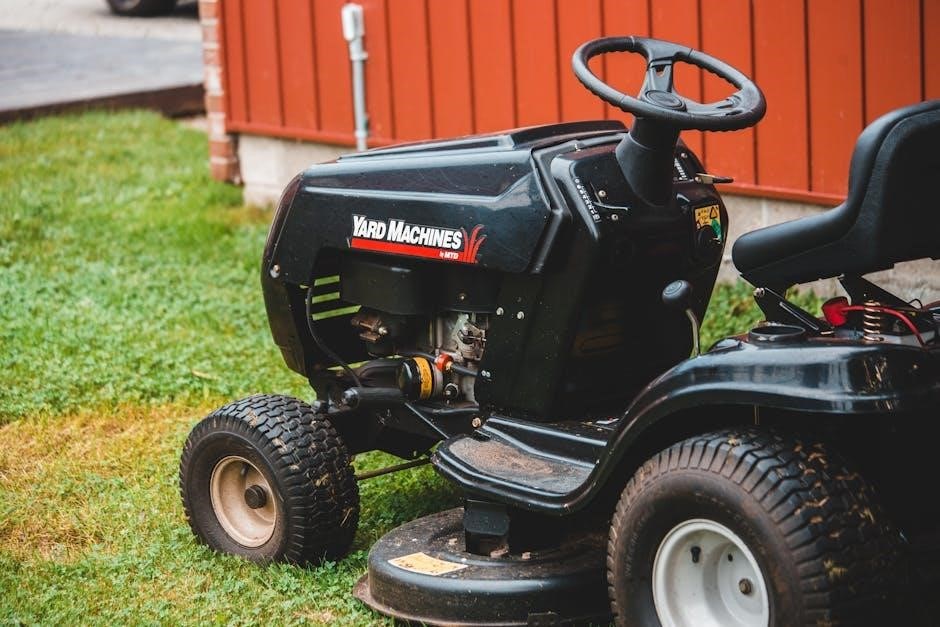
The Husqvarna YTH24V48 is a popular choice for homeowners seeking a reliable and powerful lawn tractor. Known for its 48-inch cutting deck and robust engine, it efficiently tackles various lawn sizes and conditions. However, maintaining peak performance necessitates a thorough understanding of its components and access to accurate parts information – hence the importance of a dedicated parts manual.
This particular model, frequently discussed online as of May 5th, 2026, benefits from readily available resources like customer stories, events, webinars, ebooks, and business insights, often linked through platforms like GitHub and skills-focused communities. Understanding the YTH24V48’s specific build allows for targeted repairs and preventative maintenance, extending its lifespan and ensuring optimal operation. This guide will serve as a central resource for identifying and sourcing the correct parts for your machine.
Understanding the Importance of a Parts Manual
A comprehensive parts manual is indispensable for Husqvarna YTH24V48 owners. It transcends a simple list of components; it’s a diagnostic tool, a repair guide, and a cost-saving resource. Accurate identification of parts, crucial for successful repairs, is facilitated by detailed diagrams and part numbers. Attempting repairs without proper documentation can lead to incorrect parts ordering, further damage, and increased expenses.
Considering the online resources available as of May 5th, 2026 – including customer stories, webinars, and business insights – a parts manual complements these with specific, technical details. Access to this information, alongside community support found on platforms like GitHub, empowers owners to perform maintenance confidently. A manual ensures compatibility, prevents frustration, and ultimately keeps your YTH24V48 operating efficiently for years to come.
Engine Components & Parts
Detailed breakdowns of the YTH24V48 engine, referencing updated May 5th, 2026 data, ensure correct part selection for optimal performance and longevity.
Engine Model Identification (Specific to YTH24V48)
Accurate engine identification is paramount when sourcing replacement parts for your Husqvarna YTH24V48. This model typically features a Briggs & Stratton engine, though specific variations exist depending on the year of manufacture – data current as of May 5th, 2026. Locate the engine’s model, type, and serial number stamped on the engine block, usually near the valve cover or on a dedicated identification plate.
Crucially, this information dictates compatibility. Referencing the parts manual (updated May 5th, 2026) alongside the engine’s identification details ensures you order the correct components. Common engine models found in the YTH24V48 include those starting with prefixes like “21” or “25”, followed by a series of numbers and letters. Incorrect identification can lead to wasted time, money, and potential damage to your lawn tractor. Always double-check before ordering!
Air Intake & Filtration System Parts
Maintaining a clean air intake is vital for optimal engine performance in your Husqvarna YTH24V48, as of May 5th, 2026. Key components include the air filter, pre-cleaner (if equipped), air filter housing, and intake duct. Regularly inspect and replace the air filter – paper or foam types are common – to prevent debris from entering the engine.
The parts manual details specific filter dimensions and part numbers. A clogged air filter restricts airflow, reducing power and increasing fuel consumption. Replacement intervals depend on operating conditions; dusty environments require more frequent changes. Ensure the air filter housing seals properly to prevent unfiltered air from bypassing the filter. Inspect the intake duct for cracks or damage, replacing as needed to maintain a sealed system and efficient engine operation.
Fuel System Parts (Carburetor, Fuel Pump, Fuel Lines)
The Husqvarna YTH24V48’s fuel system, as detailed in the parts manual updated May 5th, 2026, requires meticulous maintenance. Core components include the carburetor, fuel pump, fuel lines, and fuel filter; The carburetor mixes air and fuel for combustion; cleaning or rebuilding may be necessary if experiencing starting or running issues.
The fuel pump delivers fuel from the tank to the carburetor, while fuel lines transport the fuel. Inspect fuel lines for cracks, leaks, or deterioration, replacing them promptly. A fuel filter prevents debris from reaching the carburetor. Always use fresh fuel and consider a fuel stabilizer for storage. Refer to the manual for specific part numbers and diagrams to ensure correct replacement and optimal fuel delivery.
Deck & Cutting System Parts
Essential for optimal cutting performance, this section details mower deck assemblies, blades, and spindles, referencing the updated manual from May 5th, 2026.
Mower Deck Assembly Breakdown
The Husqvarna YTH24V48’s mower deck is a robust, 48-inch cutting system designed for efficient lawn maintenance. This breakdown details each component, from the deck shell itself – typically constructed from heavy-gauge steel for durability – to the mounting hardware ensuring secure attachment to the tractor chassis. We’ll explore the anti-scalp wheels, crucial for preventing damage to the lawn on uneven terrain, and their corresponding adjustment mechanisms.
Furthermore, we’ll cover the deck’s baffle system, responsible for directing airflow and creating a clean cut. Detailed diagrams, referencing the May 5th, 2026 parts manual update, illustrate the placement of each baffle and its impact on cutting quality. Understanding the deck’s internal structure, including support brackets and reinforcement plates, is vital for identifying wear and tear and performing effective repairs. Proper assembly and maintenance, guided by this breakdown, will maximize the lifespan and performance of your YTH24V48’s cutting deck.
Blade Types & Specifications
The Husqvarna YTH24V48 typically utilizes high-lift blades, designed to create strong suction for efficient grass clipping and bagging. These blades, as detailed in the updated May 5th, 2026 parts manual, are generally 16 inches in length and feature a specific cutting angle optimized for the 48-inch deck. Blade material is high-carbon steel, heat-treated for durability and resistance to wear.
Understanding blade specifications is crucial for safety and performance. The manual outlines the correct blade bolt torque and recommends replacing blades in pairs to ensure balanced cutting. Mulching blades are also compatible, offering a different cutting experience by finely chopping grass clippings and returning them to the lawn as fertilizer. Always refer to the parts manual for the correct blade part number and ensure proper installation, adhering to all safety guidelines for optimal results and longevity.
Spindle Assemblies & Bearings
The Husqvarna YTH24V48’s spindle assemblies, detailed in the May 5th, 2026 parts manual, are critical components responsible for blade rotation. Each assembly comprises a spindle shaft, housing, and bearings, enabling smooth and efficient cutting. The manual specifies that these tractors generally utilize sealed ball bearings, minimizing maintenance and protecting against debris. Regular inspection, as outlined, is vital to identify wear or damage.
Bearing failure often manifests as noise or blade wobble. The manual provides exploded diagrams illustrating the assembly’s construction and lists compatible replacement parts. Correct torque specifications for spindle mounting bolts are also included, preventing damage and ensuring safe operation. Replacing spindle assemblies or bearings requires specialized tools and adherence to safety protocols; consulting the manual and potentially a qualified technician is highly recommended for optimal performance and longevity.

Drive System & Transmission Parts
Essential for power transfer, this section—updated May 5th, 2026—details belts, hydrostatic components, and axles for the Husqvarna YTH24V48’s drive system.
Hydrostatic Transmission Components
The Husqvarna YTH24V48’s hydrostatic transmission is a crucial system, enabling smooth and variable speed control. This section details its key components, vital for maintaining optimal performance. Expect detailed breakdowns of the hydrostatic pump, responsible for converting mechanical energy into hydraulic power, and the hydraulic motor, which translates that power back into rotational force driving the wheels.
We will cover the filter, essential for maintaining hydraulic fluid cleanliness, and the drive shaft, connecting the transmission to the axle. Diagrams illustrate component placement and relationships, aiding in accurate identification during repairs or replacements. Parts lists specify compatible components, ensuring correct fit and function. Understanding these components—updated May 5th, 2026—is paramount for diagnosing issues like sluggish response, erratic movement, or complete drive failure. Proper maintenance, including fluid checks and filter replacements, extends the transmission’s lifespan and ensures continued reliable operation.
Drive Belt Diagrams & Replacement
Maintaining the drive belt system on your Husqvarna YTH24V48 is critical for transferring power from the engine to the mower deck and wheels. This section provides comprehensive diagrams illustrating belt routing for various functions – deck engagement, and forward/reverse motion. Detailed step-by-step instructions guide you through the replacement process, ensuring correct tension and alignment.
Proper belt tension is paramount; too loose, and it will slip, reducing cutting efficiency and potentially causing damage. Too tight, and it will strain the pulleys and shorten belt life. Updated May 5th, 2026, this manual specifies the correct belt types and sizes for your model. We also cover identifying wear patterns indicating the need for replacement, and troubleshooting common issues like belt fraying or breakage. Safe removal and installation techniques are emphasized, alongside recommended tools for a successful repair.
Axle & Wheel Components
The axle and wheel assembly are fundamental to the Husqvarna YTH24V48’s maneuverability and stability. This section details each component, including the axle housing, spindles, wheel hubs, and wheel bearings. Exploded diagrams, current as of May 5th, 2026, illustrate the precise arrangement of parts, facilitating accurate identification during repairs or replacements.

We provide guidance on inspecting for wear and tear, such as bent axles, damaged wheel hubs, or worn bearings, which can affect handling and tire alignment. Torque specifications for wheel lug nuts and other fasteners are clearly outlined. Instructions cover removing and installing wheels, replacing bearings, and addressing common issues like uneven tire wear. Proper maintenance of these components ensures smooth operation and extends the lifespan of your YTH24V48, contributing to a safer and more efficient mowing experience.

Electrical System Parts
Detailed diagrams and parts lists, updated May 5th, 2026, cover the YTH24V48’s battery, ignition, wiring, and safety switch components for reliable operation.
Battery & Charging System
The Husqvarna YTH24V48 utilizes a 12-volt battery to power the starting system and electrical components. This section details the battery specifications, including group size, cold cranking amps (CCA), and reserve capacity, crucial for selecting a suitable replacement. Diagrams illustrate the battery’s physical location within the tractor chassis and its connection to the charging system.
Furthermore, we provide a breakdown of the charging system, encompassing the alternator/stator, voltage regulator, and associated wiring. Troubleshooting guides assist in diagnosing common issues like insufficient charging voltage or a failed voltage regulator. Parts lists include individual components – brushes, bearings, and rectifier diodes – alongside complete alternator assemblies. Updated as of May 5th, 2026, this information ensures accurate repairs and optimal performance of the YTH24V48’s electrical foundation, referencing GitHub skills and business insights for component sourcing.
Ignition System Parts
The Husqvarna YTH24V48’s ignition system is vital for reliable engine starting and operation. This section provides detailed exploded views of the ignition coil, magneto, and flywheel assembly, updated to reflect changes as of May 5th, 2026. Parts lists specify compatible replacement components, including ignition modules, spark plugs (with gap specifications), and flywheel keys.
Troubleshooting charts guide users through diagnosing common ignition problems, such as no spark or intermittent misfires. Wiring diagrams clearly illustrate the connections between the ignition coil, safety switches, and the engine control module. We also cover the importance of proper air gap settings between the ignition coil and flywheel. Utilizing resources like business insights and skills from platforms like GitHub, we ensure accurate part identification and repair procedures for optimal engine performance and longevity.
Wiring Diagrams & Safety Switches
Understanding the Husqvarna YTH24V48’s electrical system is crucial for safe and effective repairs. This section features comprehensive wiring diagrams, current as of May 5th, 2026, detailing the connections for all electrical components. Special attention is given to safety switches – seat switches, blade engagement switches, and parking brake switches – which prevent operation under unsafe conditions.
Detailed illustrations show the location and function of each switch, alongside troubleshooting steps for identifying faulty units. Parts lists include replacement switches and connectors. We emphasize the importance of using a multimeter to verify switch continuity and voltage. Leveraging insights from events, webinars, and resources like GitHub, this manual provides a clear pathway to diagnose and resolve electrical issues, ensuring operator safety and machine functionality. Proper wiring and functioning safety switches are paramount.
Steering & Control System Parts
Explore detailed schematics and parts listings for the YTH24V48’s steering, updated May 5th, 2026, ensuring precise control and a comfortable operating experience.

Steering Wheel & Linkage
The Husqvarna YTH24V48’s steering system relies on a robust linkage connecting the steering wheel to the front axle, translating rotational movement into directional control. This section details each component, including the steering wheel itself – often available in various styles – the steering shaft, intermediate steering linkage, and pitman arm. Diagrams, updated as of May 5th, 2026, illustrate proper assembly and identify critical hardware like bolts, nuts, and cotter pins.
Troubleshooting steering issues often begins with inspecting the linkage for wear or damage. Bent or loose components can cause imprecise steering or excessive play. Replacement parts are readily available, categorized by specific model numbers to ensure compatibility. Pay close attention to torque specifications during reassembly to maintain optimal performance and safety. Detailed parts breakdowns showcase exploded views, simplifying identification and ordering of necessary replacements.

Brake System Components
Ensuring reliable stopping power is paramount for safe operation of the Husqvarna YTH24V48. This section comprehensively covers the brake system, detailing components like the brake pedal, linkage rods, brake bands, and associated hardware. Updated diagrams, current as of May 5th, 2026, clearly illustrate the assembly and function of each part. Understanding the system allows for effective troubleshooting and maintenance.
Common issues include worn brake bands, stretched linkage rods, and fluid leaks (if applicable – some models utilize hydraulic brakes). The parts manual provides exploded views for easy identification of replacement parts, categorized by specific model numbers. Proper adjustment of the brake linkage is crucial for optimal performance; detailed instructions and torque specifications are included. Regular inspection and maintenance, guided by this manual, will prolong the life of the brake system and enhance operator safety.
Seat & Operator Controls
Comfort and precise control are vital for extended operation of the Husqvarna YTH24V48. This section details the seat assembly, including the seat cushion, suspension springs (if equipped), and mounting hardware. It also covers operator controls such as the steering wheel, throttle lever, and various switches – all current as of May 5th, 2026. Detailed diagrams illustrate the placement and function of each component, aiding in repair and replacement.
Troubleshooting common issues like a loose seat or malfunctioning switches is simplified with the parts manual’s exploded views. Specific part numbers are provided for easy ordering. Proper adjustment of the seat position and control levers ensures optimal ergonomics and reduces operator fatigue. Regular inspection for wear and tear, guided by this manual, will maintain a comfortable and safe operating experience, enhancing productivity and enjoyment.