leeson motor wiring diagram pdf

A Leeson motor wiring diagram PDF provides a detailed visual guide for installing‚ troubleshooting‚ and understanding the electrical connections of Leeson motors․ These diagrams are essential for ensuring safe and proper motor operation‚ covering single-phase and three-phase configurations․
Overview of Leeson Motors and Wiring Diagrams
Leeson motors are renowned for their reliability and efficiency‚ offering a wide range of single-phase and three-phase electric motors․ These motors are widely used in industrial‚ agricultural‚ and residential applications‚ making their proper wiring essential for optimal performance․ A Leeson motor wiring diagram serves as a critical tool‚ providing a visual representation of the motor’s electrical connections․ It outlines how wires are connected to terminals‚ power sources‚ and control devices‚ ensuring safe and correct installation․ Available in PDF format‚ these diagrams are detailed and easily accessible‚ covering various motor models‚ including 1 HP‚ 1․5 HP‚ and high-torque designs․ They often include information on voltage requirements‚ terminal configurations‚ and color-coded wire connections․ For instance‚ single-phase motors may require connecting neutral and hot wires to specific terminals‚ while three-phase motors involve more complex wiring setups․ By following the diagram‚ users can avoid electrical hazards and ensure their motor operates efficiently․ Leeson motor wiring diagrams are indispensable for both professionals and DIY enthusiasts‚ offering clear guidance for installation‚ troubleshooting‚ and maintenance․
Importance of Leeson Motor Wiring Diagrams
Leeson motor wiring diagrams are essential for ensuring the safe and efficient operation of electric motors․ These diagrams provide a clear visual representation of the motor’s electrical connections‚ making it easier to install‚ troubleshoot‚ and maintain the motor․ By following the wiring diagram‚ users can avoid electrical hazards‚ such as short circuits or incorrect voltage connections‚ which could damage the motor or pose safety risks․ The diagrams are particularly useful for identifying the correct terminals for connecting power sources‚ control devices‚ and other components․ They also help in understanding voltage requirements‚ phase configurations‚ and wire color codes‚ which are critical for proper installation․ Additionally‚ wiring diagrams enable quick diagnosis of common issues‚ such as faulty connections or misconfigured wires‚ ensuring minimal downtime․ Whether for single-phase or three-phase motors‚ Leeson wiring diagrams are indispensable for professionals and DIY enthusiasts alike‚ guaranteeing optimal performance and longevity of the motor․ Their availability in PDF format makes them easily accessible and convenient to use․
How to Read a Leeson Motor Wiring Diagram
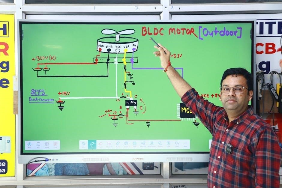
Reading a Leeson motor wiring diagram requires understanding its components and symbols․ Start by identifying the terminals‚ which are labeled on the diagram and correspond to the motor’s physical connections․ Wire colors are standardized‚ with black and red typically representing “hot” wires‚ white for neutral‚ and green for ground․ The diagram will also indicate voltage and phase requirements‚ such as 120V or 240V for single-phase motors and 208V/230V/460V for three-phase models․
Look for arrows or lines that show the flow of electricity between components․ These connections will guide you in linking the power source‚ motor‚ and any control devices․ Pay attention to specific configurations‚ such as dual voltage setups‚ which may require switching wires between high and low voltage terminals․ Always reference the motor’s nameplate for exact specifications‚ as the wiring diagram may vary depending on the model․
By carefully following the diagram and matching wire colors to their designated terminals‚ you can ensure a safe and correct installation․ If unsure‚ consult official Leeson resources or seek professional assistance to avoid electrical hazards․

Types of Leeson Motors
Leeson motors are categorized into single-phase and three-phase models‚ each designed for specific applications․ Single-phase motors are ideal for lighter loads and residential use‚ while three-phase motors suit industrial and high-power applications․ Both types require precise wiring configurations as outlined in their respective diagrams to ensure optimal performance and safety․
Single-Phase Leeson Motors
Single-phase Leeson motors are designed for applications requiring lower power and are commonly used in residential and light commercial settings․ These motors operate on a single AC power source‚ typically 120V or 240V‚ making them ideal for smaller loads such as household appliances‚ pumps‚ and fans․ The wiring configuration for single-phase motors is relatively straightforward‚ with most models requiring just two or three wires for operation‚ including a ground wire for safety․ The motor’s wiring diagram is essential for proper installation‚ as it specifies how to connect the hot‚ neutral‚ and ground wires․ Single-phase Leeson motors are known for their simplicity‚ efficiency‚ and reliability‚ making them a popular choice for applications where three-phase power is not available․ Their compact design and ease of use ensure they meet the needs of various industries while maintaining optimal performance․ Always refer to the official Leeson motor wiring diagram PDF for specific instructions tailored to your motor model․
Three-Phase Leeson Motors
Three-phase Leeson motors are designed for industrial and commercial applications requiring higher power and efficiency․ These motors operate on three AC power lines‚ providing smoother operation and higher torque compared to single-phase motors․ The wiring configuration for three-phase motors is more complex‚ typically involving three “hot” wires and a ground wire․ The motor’s wiring diagram is crucial for proper installation‚ as it outlines the correct connections for the terminals to ensure safe and efficient operation․ Three-phase Leeson motors are commonly used in heavy machinery‚ pumps‚ and industrial equipment‚ where reliable performance is critical; They are available in various voltage ratings‚ including 208V‚ 240V‚ and 480V‚ making them versatile for different industrial settings․ Always refer to the official Leeson motor wiring diagram PDF for specific instructions‚ as improper wiring can lead to motor damage or safety hazards․ Proper installation ensures optimal performance‚ longevity‚ and safety in industrial environments․
Downloading Leeson Motor Wiring Diagrams
Leeson motor wiring diagrams are available for download in PDF format from official sources and third-party websites․ These diagrams provide detailed information on motor connections‚ voltage requirements‚ and troubleshooting‚ ensuring safe and proper installation․
Official Sources for Leeson Motor Wiring Diagrams
Official Leeson motor wiring diagrams can be downloaded directly from the Leeson website or through authorized distributors like the Dri-Vac Corporation․ These sources provide PDF files that include detailed schematics‚ terminal connections‚ and voltage requirements for various motor models․
The diagrams are categorized by motor type‚ such as single-phase and three-phase configurations‚ ensuring users can find the specific information they need․ Official sources also offer guides for dual voltage motors and advanced configurations‚ making them indispensable for installers and technicians․
By using official sources‚ users can ensure the accuracy and safety of their wiring connections․ These resources are regularly updated and verified by Leeson experts‚ providing reliable instructions for installation‚ troubleshooting‚ and maintenance․ For added convenience‚ many official sources include supplementary materials like user manuals and technical support contacts․
Visitors can access these diagrams by visiting the Leeson website or contacting authorized partners like Dri-Vac Corporation at their official website or through their customer service team․ This ensures a seamless experience for professionals and DIY enthusiasts alike․

Installation and Wiring of Leeson Motors
Connect the neutral and hot wires from the power source to the designated terminals on the motor․ Use a meter to verify resistance between conductors․ Ensure proper voltage configuration‚ referencing the wiring diagram for specific models like the Leeson C4C17NH12B․ Always follow safety guidelines and manufacturer instructions for a secure setup․
General Installation Steps
Installing a Leeson motor requires careful planning and adherence to the wiring diagram․ Begin by gathering tools‚ including a multimeter and wire strippers․ Ensure the motor is properly grounded for safety․ Connect the neutral and hot wires from the power source to the designated terminals‚ referencing the diagram for correct placement․ For single-phase motors‚ verify the voltage configuration (e․g․‚ 120V or 240V) and ensure the wiring matches the specified setup․ Use a multimeter to check resistance between terminals to confirm proper connections․ Secure all wires with cable ties or clips to prevent loose connections․ Double-check the wiring configuration for features like reversible rotation or dual voltage if applicable․ Finally‚ test the motor at a low voltage to ensure smooth operation before full-power startup․ Always follow safety guidelines and manufacturer instructions to avoid electrical hazards and ensure optimal performance․

Troubleshooting Leeson Motor Wiring Issues
Common issues include incorrect voltage connections‚ loose wires‚ or phase imbalances․ Use a multimeter to verify resistance and voltage․ Check for short circuits or open circuits․ Consult the wiring diagram to ensure proper terminal connections and configurations․
Common Wiring Issues and Solutions
When working with Leeson motor wiring diagrams‚ common issues include incorrect voltage connections‚ loose wires‚ or phase imbalances․ A multimeter can help verify resistance and voltage levels․ If the motor fails to start‚ check for short circuits or open circuits between terminals․
- Incorrect Voltage Connections: Ensure the motor is wired for the correct voltage (120V or 240V) as specified in the diagram․ Misconfiguration can damage the motor or cause it to overheat․
- Loose Connections: Tighten all wire connections to prevent arcing or intermittent operation․ Use wire nuts or solder for secure joints․
- Phase Imbalances: For three-phase motors‚ ensure all phases are properly connected and balanced․ Uneven phases can lead to reduced efficiency or motor failure․
- Motor Rotation Issues: If the motor rotates in the wrong direction‚ reverse two of the phase wires (for three-phase motors) or check the wiring diagram for single-phase models․
Always refer to the wiring diagram and use proper tools to diagnose and resolve issues․ Correcting these problems ensures safe and efficient motor operation․

Advanced Configurations for Leeson Motors
Leeson motor wiring diagrams support advanced setups like dual voltage configurations‚ enabling motors to operate at multiple voltages․ These diagrams also guide multi-phase wiring and speed control configurations‚ ensuring optimal performance for complex applications․

Dual Voltage Motor Wiring
Dual voltage motor wiring allows Leeson motors to operate at two different voltage levels‚ such as 120V and 240V‚ providing flexibility for various applications․ The wiring diagram specifies how to connect the motor’s terminals for each voltage configuration․ For example‚ in a 120/240V motor‚ the diagram shows how to wire the terminals for low or high voltage by connecting or bypassing specific windings․ This setup ensures the motor runs efficiently at either voltage without damage․ The diagrams often include color-coded wires and terminal markings to guide the connections accurately․ Proper configuration is critical to avoid motor damage or electrical hazards․ By following the dual voltage wiring instructions‚ users can adapt their Leeson motor to different power sources‚ making it suitable for a wide range of industrial and residential applications․ Always refer to the official Leeson motor wiring diagram for precise instructions tailored to your specific motor model․

Resources and Support for Leeson Motor Wiring
Leeson motor wiring diagrams and guides are available through official sources like Leeson’s website and third-party communities․ These resources provide comprehensive support‚ including PDF downloads‚ troubleshooting tips‚ and expert advice for optimal motor performance and safety․
Official Leeson Motor Resources
Official Leeson motor resources provide reliable and comprehensive support for wiring and installation․ The Leeson website offers downloadable PDF wiring diagrams‚ user manuals‚ and technical specifications for various motor models․ These resources are designed to ensure safe and accurate connections‚ covering both single-phase and three-phase configurations․ Additionally‚ Leeson’s official documentation includes detailed guides for troubleshooting common issues and optimizing motor performance․ Users can access these materials directly from the Leeson website‚ ensuring authenticity and relevance․ The resources are regularly updated to reflect the latest motor models and wiring standards․ For specific models‚ such as the Leeson C4C17NH12B or C6C17NB47C‚ official diagrams provide clear instructions for voltage configurations and terminal connections․ These official resources are indispensable for professionals and DIYers alike‚ offering a trusted foundation for successful motor wiring projects․
Third-Party Resources and Communities
Beyond official sources‚ third-party resources and communities offer valuable support for understanding and working with Leeson motor wiring diagrams․ Websites like wiringname․com provide free downloadable PDFs of wiring diagrams for various Leeson motor models‚ including single-phase and three-phase configurations․ These resources often include step-by-step guides and troubleshooting tips‚ making them accessible to both professionals and DIY enthusiasts․ Additionally‚ online forums and communities‚ such as those dedicated to electrical engineering or motor repair‚ frequently discuss Leeson motor wiring․ Users share their experiences‚ solutions to common issues‚ and interpretations of complex diagrams․ For example‚ discussions about models like the Leeson C4C17NH12B or C6C17NB47C often include detailed wiring instructions and real-world applications․ These third-party resources complement official documentation by offering practical insights and alternative perspectives‚ helping users overcome challenges and optimize their motor setups․ They are particularly useful for those seeking hands-on advice or clarification on specific wiring scenarios;
Leeson motor wiring diagrams are indispensable tools for ensuring the safe and efficient operation of Leeson motors․ By providing clear‚ detailed visual representations of electrical connections‚ these diagrams help users avoid potential hazards and optimize motor performance․ Whether for installation‚ troubleshooting‚ or advanced configurations‚ Leeson wiring diagrams are essential for both professionals and DIY enthusiasts․ Their availability in PDF format from official sources like Leeson’s website‚ as well as third-party platforms‚ makes them easily accessible․ These resources empower users to understand and work with single-phase and three-phase motors confidently․ By following the guidelines and instructions provided in these diagrams‚ individuals can ensure their motors function correctly and safely; Leeson motor wiring diagrams are a cornerstone of motor maintenance and installation‚ offering clarity and precision in every step of the process․


